2/3/06
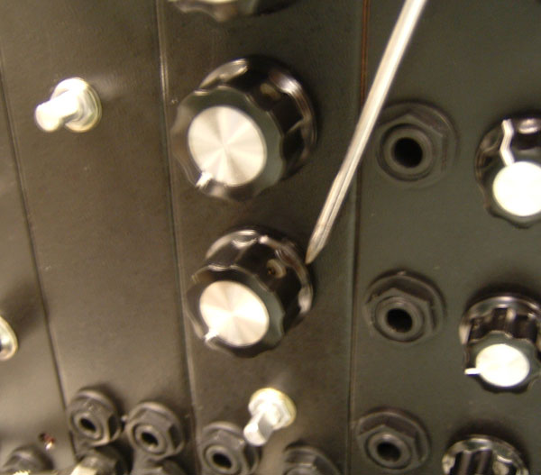
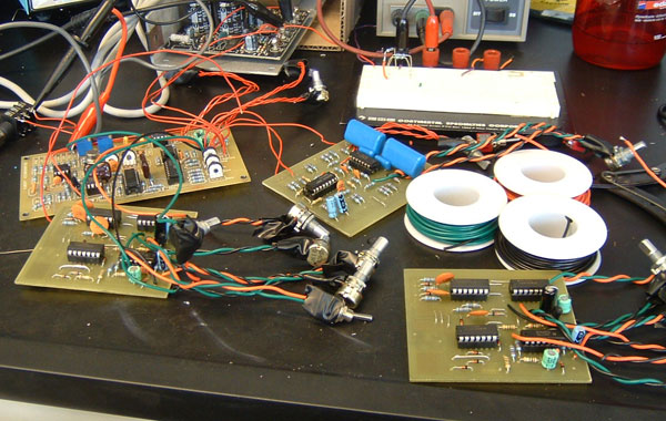
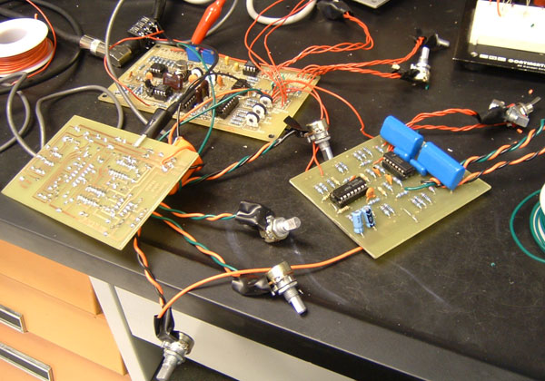
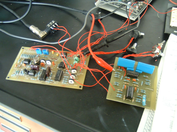
Today was the last day in the lab, I was basically debugging all day. I made sure all of the pots and switches were turing right and all the jacks were in the right place along with making sure all the modules were still working OK. Here I am checking out one of the ADSRs.
When a module was working 100% perfectly, I put its knobs on... that way it was easy to keep track of what was finished and what wasn't.
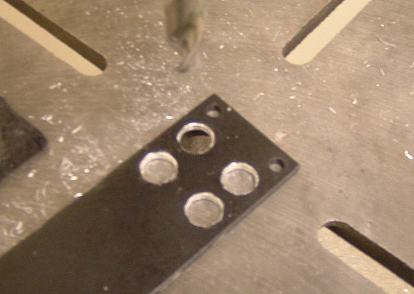
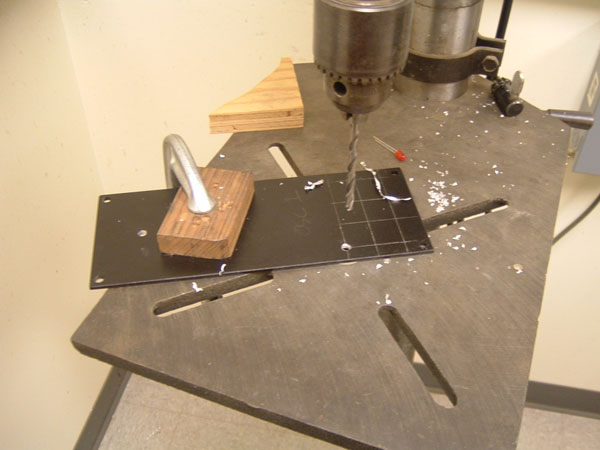
I also had time today to finish up the LPF. Here I am drilling the panel for it.
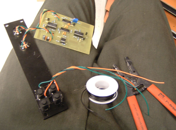
And here I am wiring it up. It worked 100% perfectly first try.
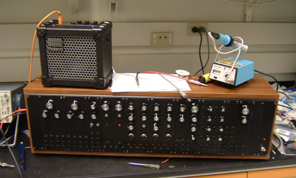
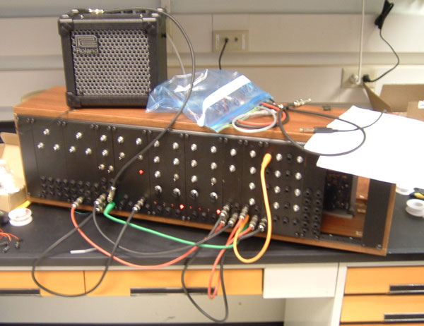
Finally... one month later, the synth is done.
2/2/06
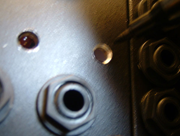
The first thing I did today was color over the silver rings around the LED holes with a black marker, so that it didn't look so obvious. Not an easy thing to take a picture of!
Next, I wired up Ken Stone's "stompbox adapters", so that I can use my pedals as modules and my modules as pedals.
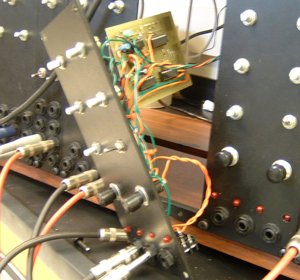
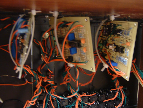
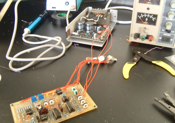
Here I am finally wiring up the power. Sorry for the terrible picture, it was very hard to get inside and get a nice one.
Finally, the synth is singing! The ADSRs and one of the LFOs is working kind of funky but I will hopefully be able to fix both tomorrow.
2/1/06
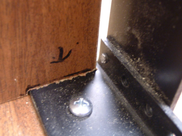
My camera's batteries are recharged so here are some pictures of what I did yesterday. Here are the "inserts", which allow the sides to slide over the rack rails. They were done using a milling machine but I'm sure you could do them fine with a router or even a dremel. The other problem with this overlapping technique is that it limits what side panels you can use-one of mine is a power switch which should be OK but on the other side I have to figure out something that doesn't span both "columns" if you know what I mean.
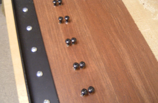
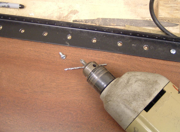
Yesterday I also drilled all of these screws along the top. When buying wire ties, I had an epiphany as to how to mount my PCBs-drill screws along the top and "hang" the PCBs via wire ties from the screws. It works well (more pictures below). These are the same fat-head screws like the ones I Used to mount the rack rails, but they are a bit longer.
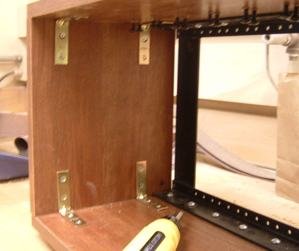
Here I am marking out where to drill for the L-brackets on the sides.
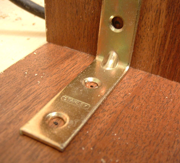
Putting all of the L-brackets in is a real balancing act... it is hard to drill the holes perfectly so I had to slowly put each screw in to make the sides as flush as possible to the top and bottom. After a lot of careful tweaking, I was still a tiny bit off on one side, but so it goes.
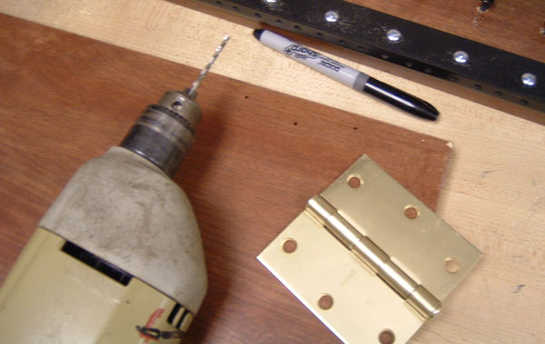
Next up are the hinges for the 10" wide back panel. Here the holes are marked and I am ready to drill.
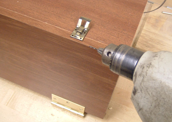
After the hinges come the latches (the package called them catches, I don't know why). The screws for these were tiny.
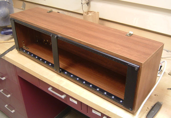
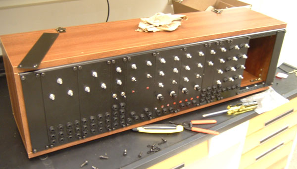
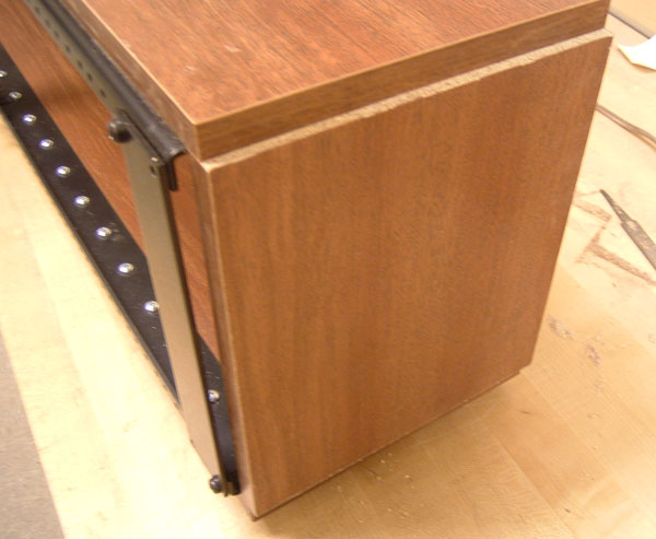
Finally, the cabinet is done!
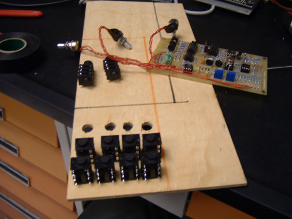
During the morning, while I was waiting to be let into the machine shop, I put all of the rest of the modules into their panels and wired up the mixer panel, which I am finishing here.
A synth!... sort of. I put all of the panels in where they should go. It was sort of a pain because my jacks were all a little bit low-tomorrow I have to redrill a few holes on one of the ADSRs so it can fit on the rack rails better (you can see the missing screws if you look carefully). Tomorrow the knobs will come and the LEDs will REALLY be mounted.
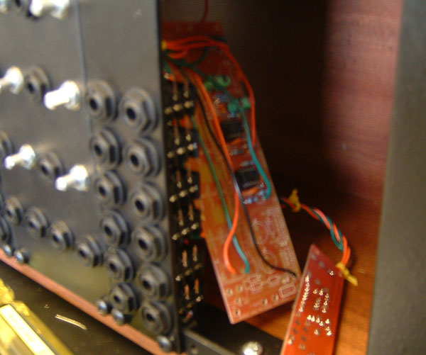
After the modules were in, I "hung" the PCBs with wire ties. It works really well. I think they will be pretty hard to shake out, and they are certainly easy to get out as long as you don't mind cutting a few wire ties. Each module took 2 wire ties.
1/31/06
Today, I made up the sides. Here I marked out how large to cut out pieces from the shelf, it turned out to be about 9 1/4".
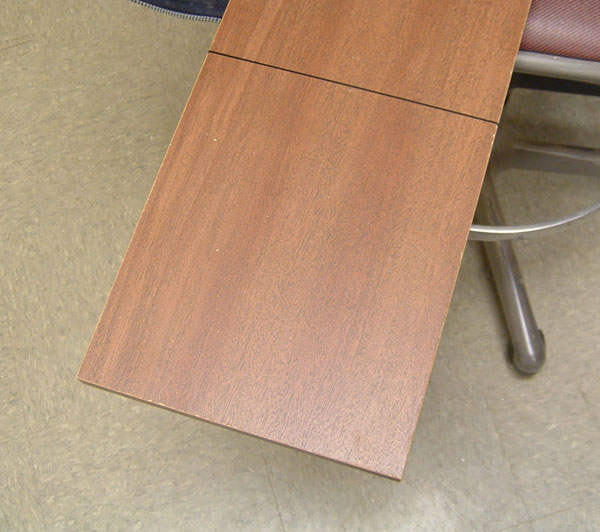
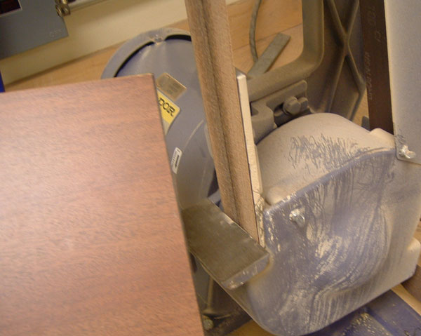
After cutting, I sanded them to the perfect size with the belt sander (man am I lucky to have all of this equipment!)
Here is how they will fit between the top and bottom to give you an idea. This is how they fit without the inserts cut away to allow them to slide in over the rack rails on top and bottom. When they do slide in, no ugly cuts will be visible.
While waiting for the machinist to get in to help me cut the inserts, I started mounting circuits in their panels. Here one of the VCOs is going in.
While taking my next picture, of the VCO completely in with wire ties and all, my camera died. Tomorrow I will update with pictures of the inserts cut out and all.
1/30/06
I finished off the drilling this morning. Here are all of the modules drilled.
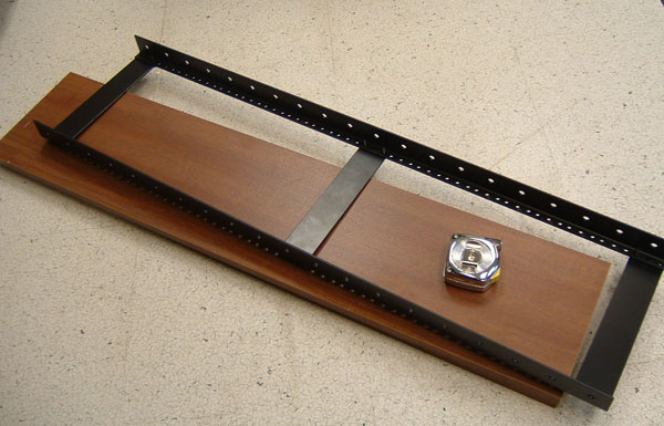
The next thing to do is my cabinet. I am going to take more pictures from now on in hopes of making a semi-tutorial as there is not too much good information on cabinet building on the net, except for the synthesizers.com DIY cabinet tutorial, which I am basing mine off of. I bought 3 8" by 36" shelves and one 10" by 36" shelf from Home Depot, rack rails and various screws from eBay user dblittlea, and some various screws from the hardware store. First off I measured the shelves and the rack rails...
So that I could figure out where to drill the screws on either side (which must be short in length, around 1/2", but still have a very fat head).
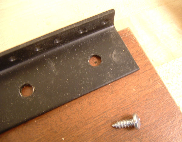
And then I simply went through and drilled all of the remaining holes, being careful not to drill through (which I unfortunately did, but fortunately I got to pick which was the top and bottom, so the holes will never be visible). You may want to note that my rack rails are slightly overhanging the shelves (more obvious in the next picture). This is because the shelves I bought were just a bit too short to accomodate the rack rails AND the sides with the sides sandwiched in between the top and bottom. To fix this, I need inserts in the sides that allow them to slide over the rack rails. You can avoid this problem by either getting larger shelves and cutting them or by mounting the sides so that they are not sandwiched between the top and bottom... though in these cases you will be able to see the cuts. More on the slots later.
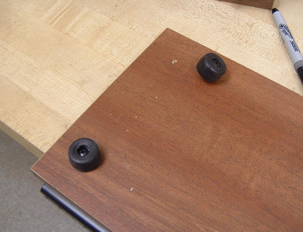
I also drilled holes for and mounted the rubber feet on the bottom, which I got from the guy who sold me the rack rails.
1/28/06
I started drilling today. Here is my general setup, where I am drilling pilot holes on my VCO with the drill press.
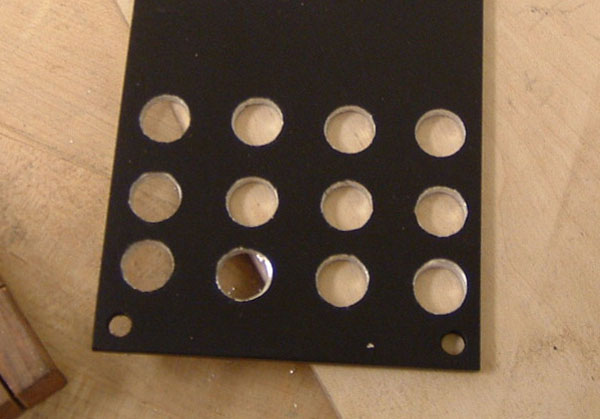
After the pilot holes come the actual-size holes (is there a real word for that?). These are the 12 holes for the jacks on the VCO.
1/27/06
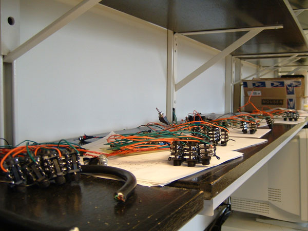
Today, in the morning, I finished all of the jacks. Here are all of the modules on their shelf with all of their jacks.
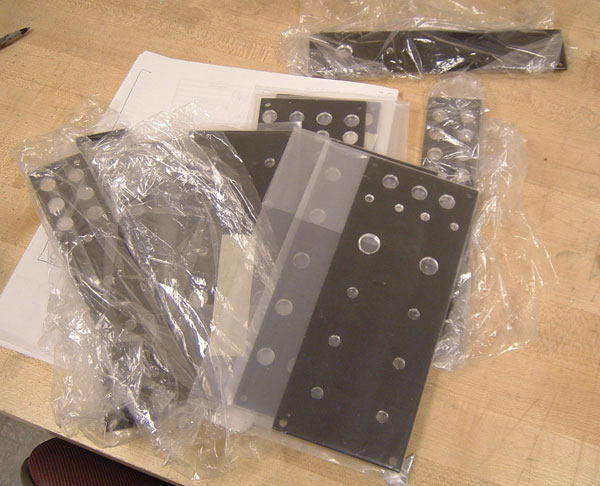
The panels finally arrived today. Thank goodness for overnight shipping, otherwise I don't think I would have received them before the end of Winter Term.
To mark out the panels, I first made a sort of template on paper with a shape for 1U and 2U space panels and lines for where the knobs, jacks, etc should go in proper divisions. It worked out quite well. The panels are about 8.75" and if you go 1.25" from the top for the first row of knobs and 1.5" from the bottom for the divider for the bottom two rows of jacks, you have a perfect 6" which you can divide into 4 1.5" sections for the remaining 5 "rows". Here I have layed out what my VCOs will look like. Next to the template is my "rough sketch" of the VCO panel... There is one extra jack now because I decided if I have a row of 3 I may as well make it 4 with an added Lin CV in jack.
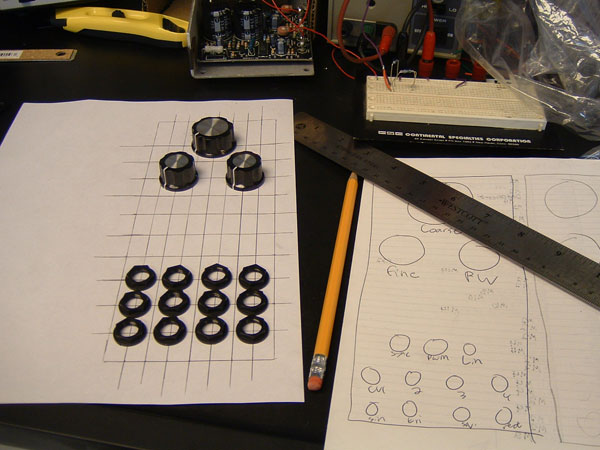
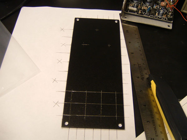
Then I simply placed the panels on the template and used a razor to mark (on the back of the panel) where to drill. Here is the VCO panel all marked out (look carefully to see the marks).
1/26/06
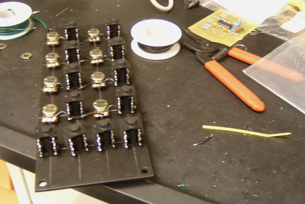
Last night I emailed MOTM to ask if my panels had shipped-they hadn't 8 days after the order was placed, so I had them shipped overnight. So, while I was still waiting, I used the template to wire up a bunch of the jacks for the modules. There's lots of them!
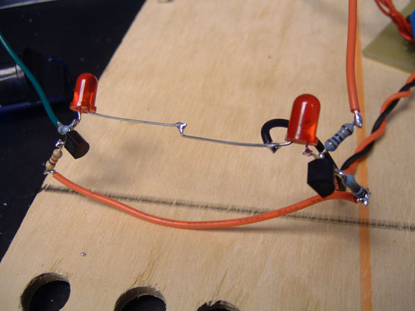
I also had to do misc other things like wire up the LED assembly for the LFO.
At the end of the day I took a bus to Home Depot and Radioshack to get shelves, L-brackets, screws, etc for the cabinet and some more wire because I was running low.
1/25/06
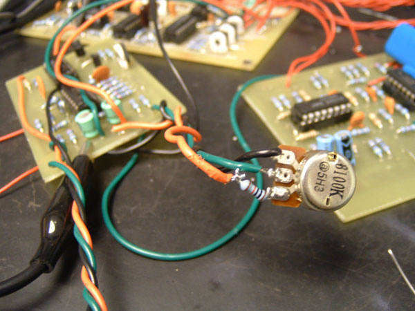
My panels still haven't arrived from MOTM, so today I tweaked the VCF a bit because the upper range was much too high. I also tried to add ramp/saw functionality to the LFO but it didn't quite work... and it's not really worth it with the way the LFO is set up (sour grapes?) Here is the VCF with the resistor added to the pot to get the high range down-I put a 10k resistor in.
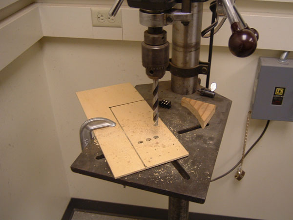
I decided it was silly to wait until the panels arrived and were drilled to wire up the jacks if the panels still weren't here, so I made a wooden "template" for modules, with spots for any arrangement of jacks so I can wire them in the proper place. Here I am drilling it.
1/24/06
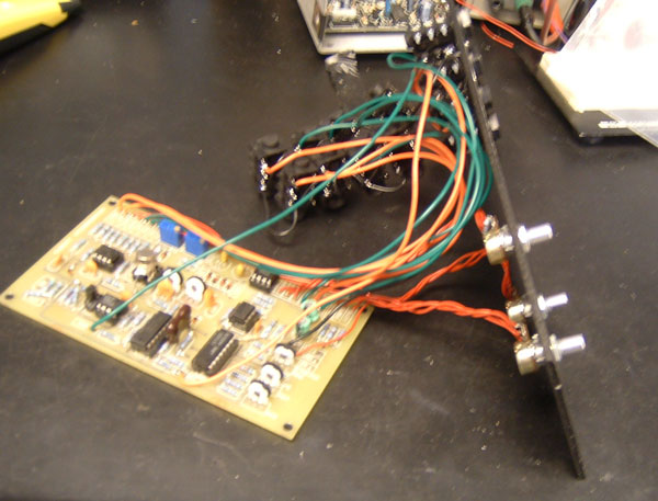
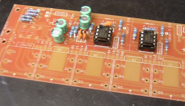
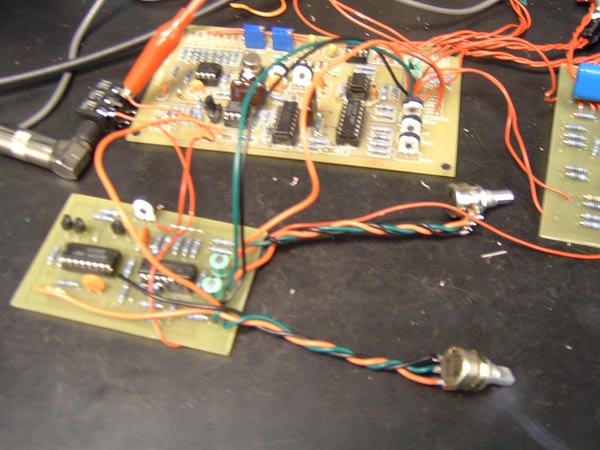
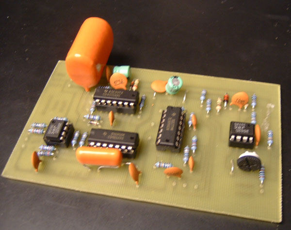
There is not too much I can do until my module panels come in from MOTM, so today I finished some of the modules that I wasn't sure if I'd ahve time for over winter term: The second pedal/CV converter, which as you can see is missing a couple of parts which will be on their way soon...
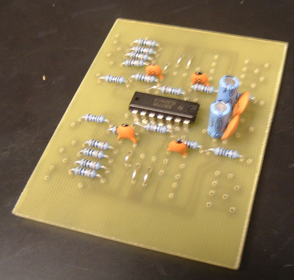
And the Low Pass Filter. Most of what's missing is actually 100k resistors which I managed to run out of!
1/23/06
Today I just went back and tried to get the VCO to work in the range I wanted it to at +/-15v. The changes I made were c6 to .01uf and series resistors to limit the range on both the coarse adjustment pot and the pulse width pot. In +/-15v for some reason the oscillation dies lower than about -10v, so I kept that from happening.
1/19/06
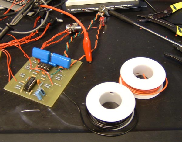
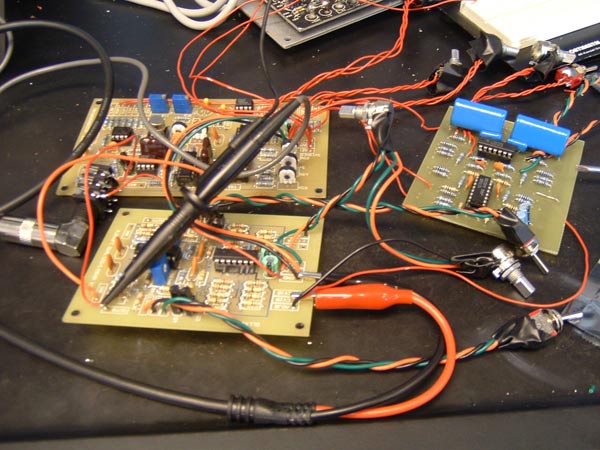
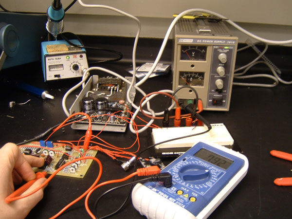
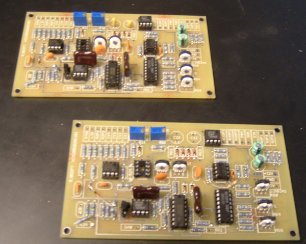
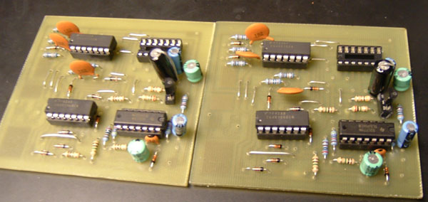
I started out today testing the ADSRs. They both worked just fine, but were a bit of a pain to test because I don't have a good gate/trigger source yet. I tried using an LFO offset to oscillate from about 2v to 8v, but just ended up blowing up one of the chips! A replacement is on the way... shown here is both boards, with one being tested.
The last module to wire up and test was the sample and hold, which worked great after some soldering problems were sorted...
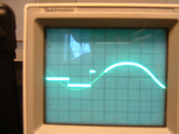
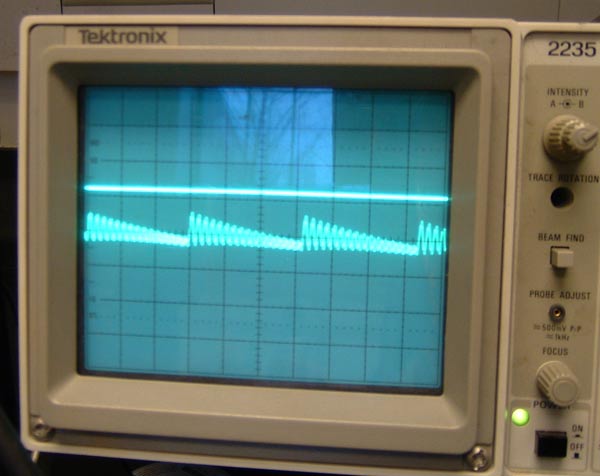
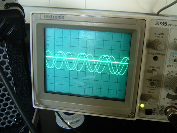
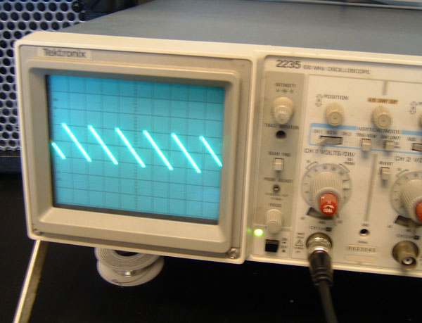
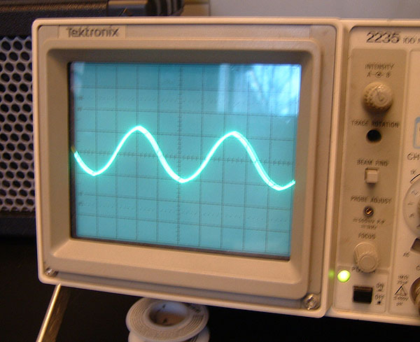
It was hard to get a good picture of the S+H in action, but here is my best shot... this is a sine wave LFO into the sample and hold. The oscilloscope is tracking slowly so the first set of lines you see is the sine wave being tracked while the curve is the actual sine wave. See?
1/18/06
Last night, I was able to get some new wire from Radioshack, so I wired up the other half of the LFO first. 3 wire colors are better than one...
After the LFO was working fine, I wired up the VCA, which needed a tad of odd adjustment because of the +/-15v supply. I have it working as I want it to now though.
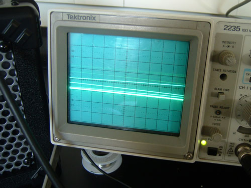
Here is the VCA in action, the straight line is the CV from the LFO, which controls the amplitude of the VCO. Now that I am starting to wire up the subtractive modules, I need to have the LFO and VCO on hand all the time, which is kind of a pain.
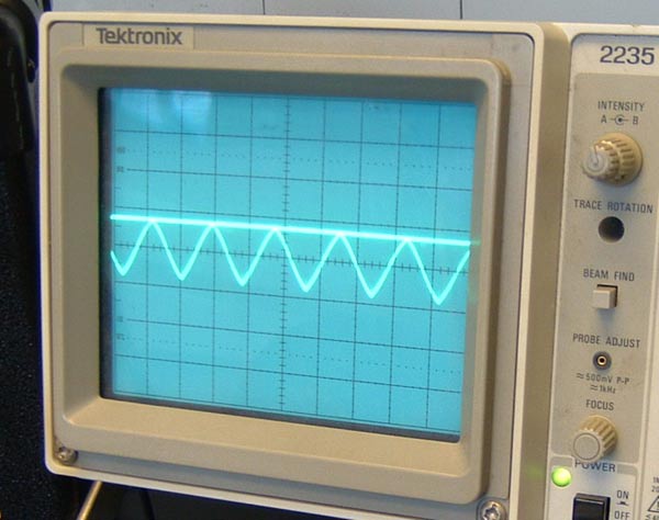
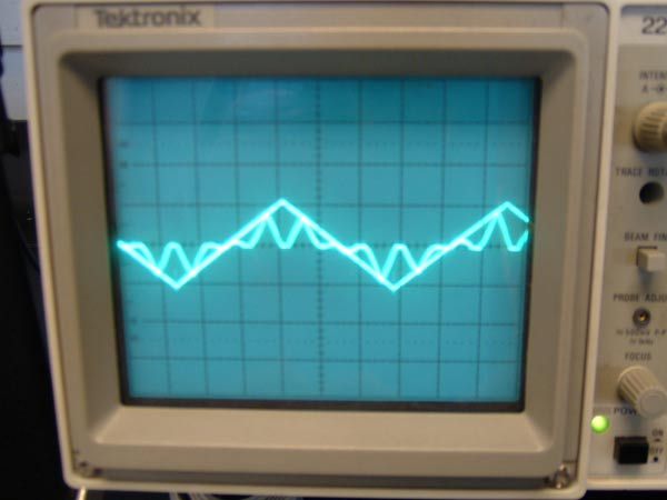
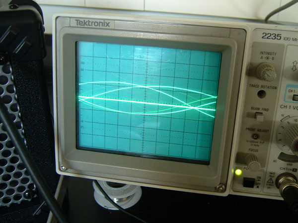
The VCO can also do interesting things at higher frequencies... Here I have rigged up the LFO to run at a higher frequency, so that the input is ring modulated... the plain triangle wave is the "clean" signal, the jagged lines inside are what happens after it is modulated by the higher frequency.
Next up was the state-variable filter, which worked flawlessly right away, though I think I am going to need to tweak the upper range of the circuit because at higher Qs it oscillates, and the top frequency is simply much too high as it is.
Here is one of the fun things you can do... this is a lowpass filter with high Q filtering a ramp wave. I wish you could hear it, it's very cymbal like, like a ring modulator with really interesting timbres.
1/17/06
Today, since I don't have any hookup wire and am awaiting a ride to radioshack to get some, I did some research on the net for my cabinet. I plan on building a cabinet from the synthesizer.com DIY cabinet page...

But instead of using wood inserts, I'm going to use rack rails, which I will probably get from eBay...

And mount MOTM blank panels, which I'll drill myself. A bit more planning will have to go into it when I get everything, but the final result will allow a lot of customizability (is that a word?) and look very nice, something like the below. There is not too much info on the net about this sort of thing so hopefully I can provide some sort of a guide. Now if I can get some hookup wire, I can finish some more modules...

1/16/06
For the last few days I have been debugging my VCOs and the LFO. One VCO was having a problem with an oscillation in the tuning circuitry, so that there was this very high pitched oscillation all over the board... But a careful re-doing of the solder joints fixed it. Here's a lesson... in high gain op-amp circuits, flux and cold joints can make oscillations. Here it is all set up, with a clean high frequency triangle wave! (Finally)
To further test the VCO and LFO, I tested each of the VCO's CV points and the PWM in. Here the LFO is hooked up to the VCO board... it's interesting because soldering wires is the same as patching here and there, just quite a bit more tedious :)
It is hard to show how the LFO is cycling the frequency, but I did my best. The oscilloscope is showing two lines-one, the sine output of the VCO, and the other, the sine output of the LFO (the line). As the line (voltage) gets higher, the frequency gets higher. Each line on the Oscilloscope's graph represents 5v, we are cycling from + to - 10v.
When the line (voltage) gets lower, you can see the frequency decrease...
And finally when it gets closer to -10v, the VCO's output gets more like a line because of the oscilloscope setting. Unfortunately, at this point I ran out of wire, so I couldn't do much more.
1/12/06
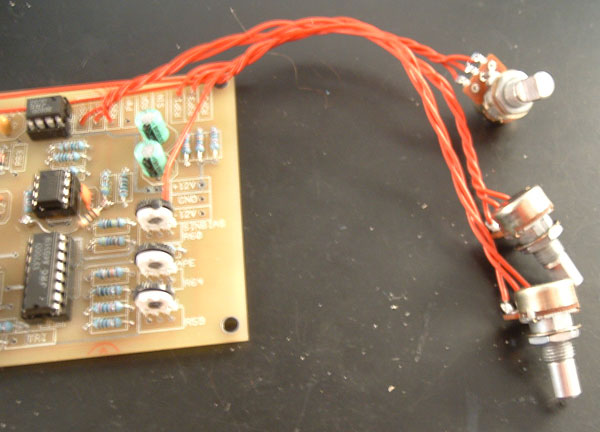
Today my synth made its first sounds! Because I have all of my PCBs done, the next step is calibrating and fixing all of my mistakes. I started with the core of my modular-both VCOs. In order for them to work, I needed to put the pots in...
Then I connected it to the power supply I bought and fixed up...
And sure enough, it started generating waveforms. At the core of Ray's VCOs is the ramp generating circuitry, so you need that calibrating and working before the rest works. Here is the sawtooth with the correct offset.
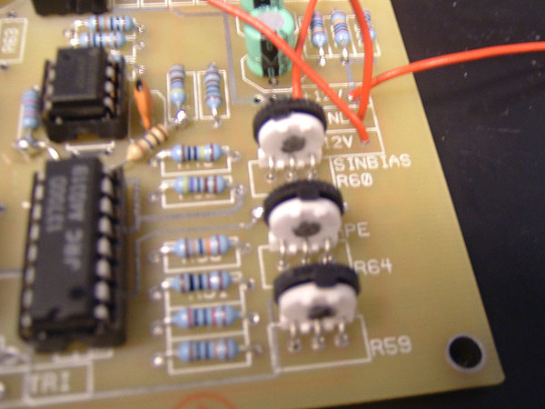
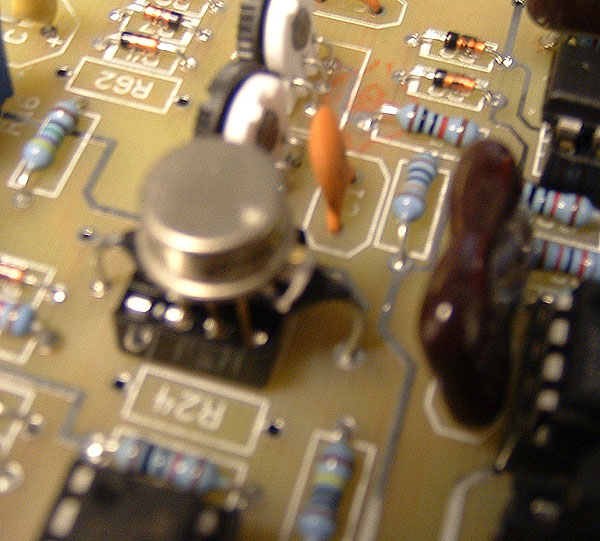
After setting the triangle offset, the sine wave must be calibrated, which involves the bias, its height, and its shape, all controlled by the distorting LM13700. Here are the three trimpots which must be adjusted together to get the right wave.
And here is the sine wave-although this is not yet perfectly adjusted in this picture. But at least its working, right?!
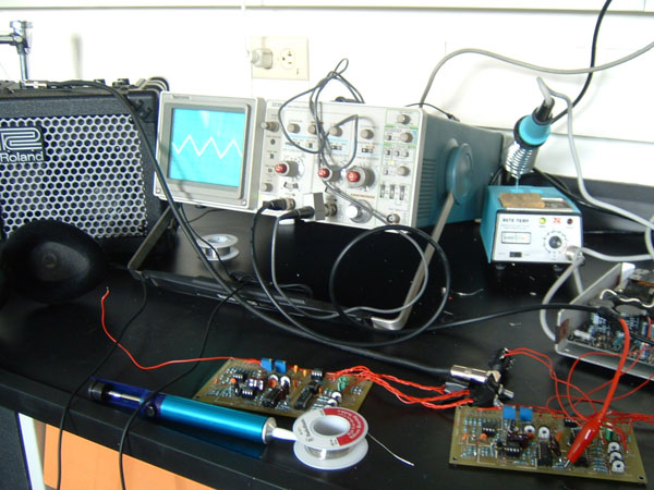
The final step to getting these VCOs working perfectly is tweaking their 1v/octave response, which is sort of a tedious process because you have to adjust one thing, then another, then another, then readjust the first, then readjust the next, then adjust something else, until it is as close to perfect as possible. I got fairly close today with one VCO, but the other one is acting kind of funky, so tomorrow I will see if I can debug it at all. Here is a picture of the setup for tweaking the 1v/octave response.
1/11/06
First off today, I borrowed some thermal grease from the electronic technician here at Oberlin to heatsink the temperature controlled resistor to the LM394 on both of the VCO boards. Here I am applying the compound...
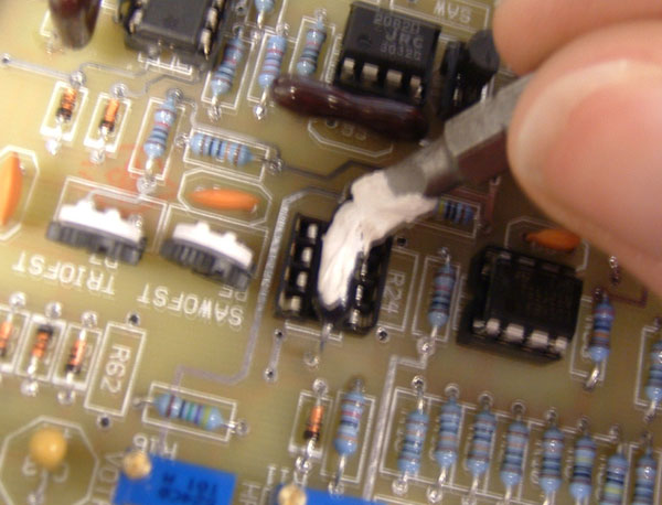
And here is the finished product, a sandwich of an LM394 on top, thermal grease, the TCR, and the socket.
I finished all of the rest of the boards I am going to be doing right now today. First, the dual LFO... look at the big 2u2 caps, they make the LFOs cycle in minutes...
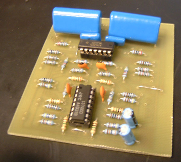
Next, the noise and S+H... I decided to get some mythical Orange Drop capacitors for fun from Mouser, you can see here it was sort of a silly idea (that is a 1uf one).
Finally, the dual DC mixer, done on Ray's very cool multi-purpose TL084 board.
1/10/06
I forgot to bring my camera in yesterday, but the whole day was spent carefully soldering the VCO boards. The VCOs have this sort of very picky and fragile feeling to them just because of all of the temperature compensation parts that go into them, so I was extra careful to make sure everything was oriented OK. As you can see, the LM394 and PT140 temperature constant resistor aren't in there yet... I am going to put them in when I start calibrating these.
There were some funky things I had to do because of the revisions Ray made, like mount this weird diode sculpture sort of thing:
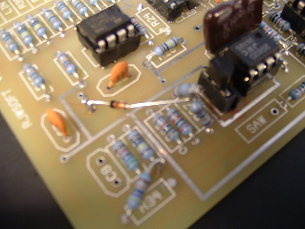
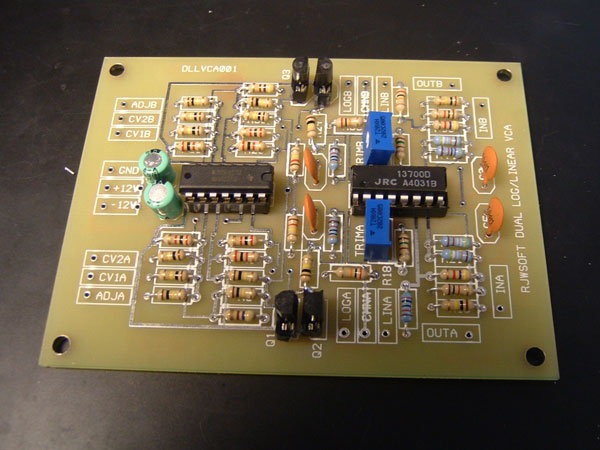
The first board I did today was the dual log/linear VCA. Here it is in completed form.
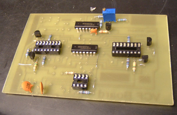
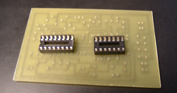
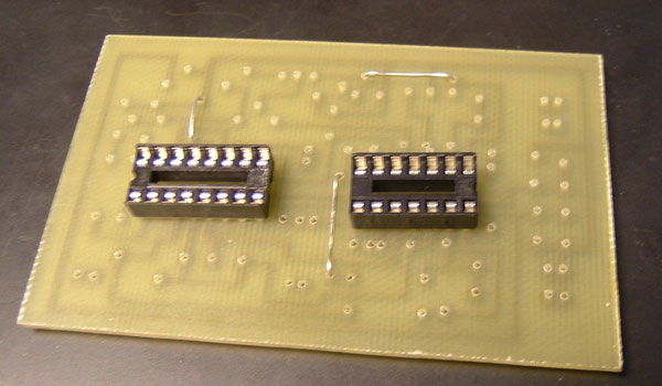
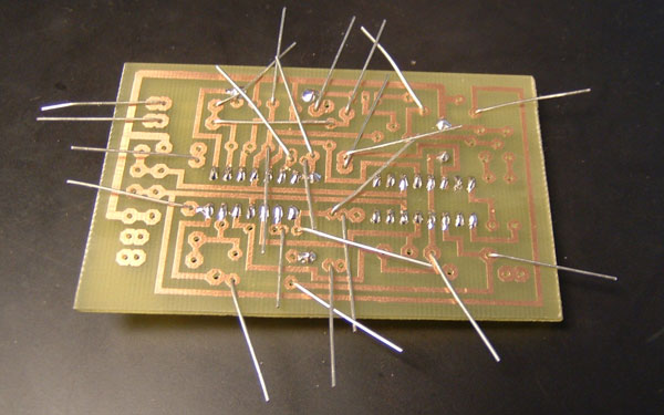
Because the assembly of the circuit boards is generally the same, I thought it would be boring for me to post pics of various steps of each board-instead, here is the VC SV Filter from beginning to end, step by step. FIrst go the IC sockets (I sometimes socket transistors too if it's convenient).
Some boards need jumpers, which go in next...
This is how I put in my resistors and caps before soldering them... keeps them in place, you just have to be careful that your bent leads are not going onto a pad you are going to be soldering. Since it can get a bit messy, if there are lots of resistors I normally do half at a time.
Here are all of the resistors soldered in...
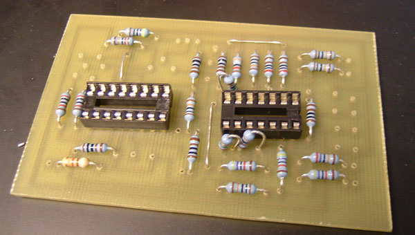
Then capacitors...
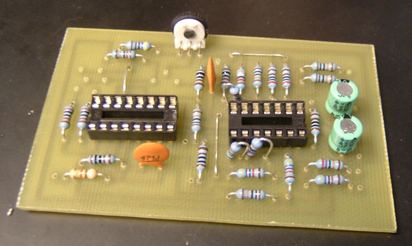
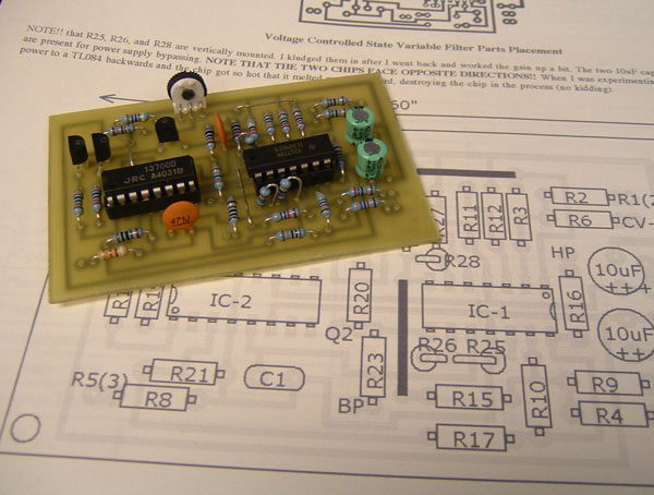
Finally, all semi's and trimpots go in. Here is the finished PCB on top of a printout of Ray's site for reference.
Today, I also finished both ADSR boards.
1/06/06
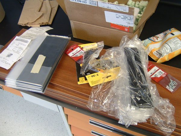
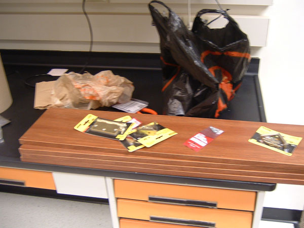
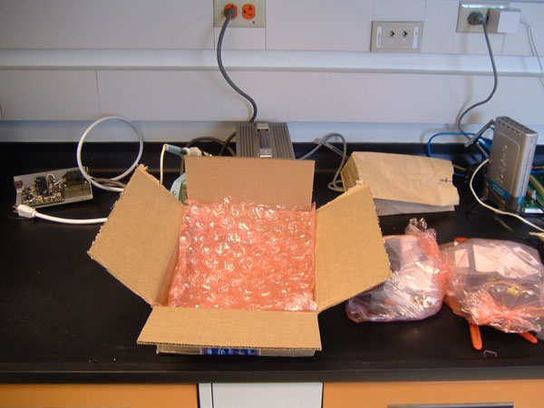
The big order from Mouser came in.
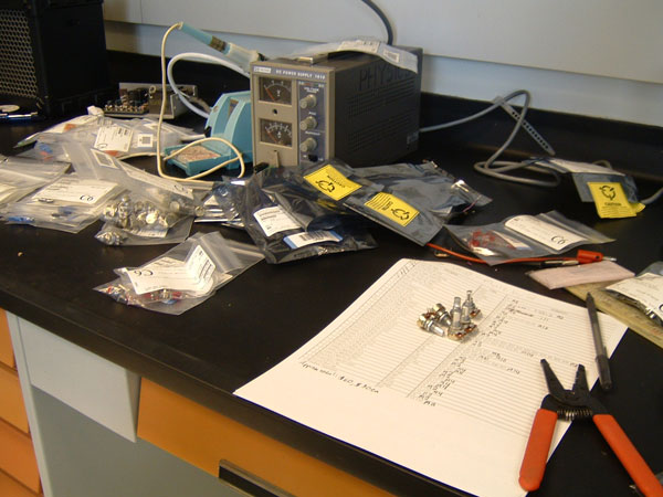
Here I'md sorting out all of the parts by module.
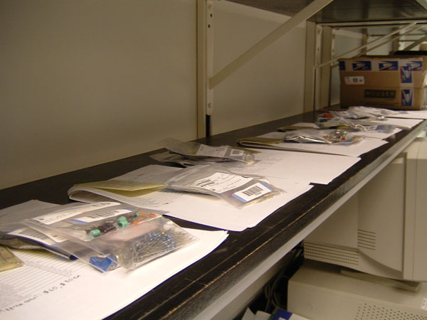
Here are all the parts sorted.
1/04/06
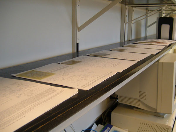
Today, the parts order from Mouser hadn't come in yet, so I just organized the area and set out printouts of all of the module's sites and PCBs together.
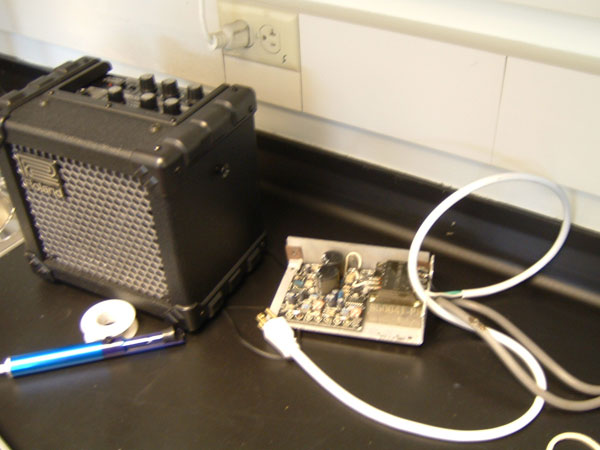
I did receive the powerone +/- 15v power supply, but it didn't have an AC line chord, so I soldered it on and got it calibrated. I also brought in my microcube, because an oscilloscope just isn't enough!
|
|